What is the installation process of the warehouse?
06/29/2023
First of all, it is necessary to locate the foundation position, install the embedded parts, and pour concrete.
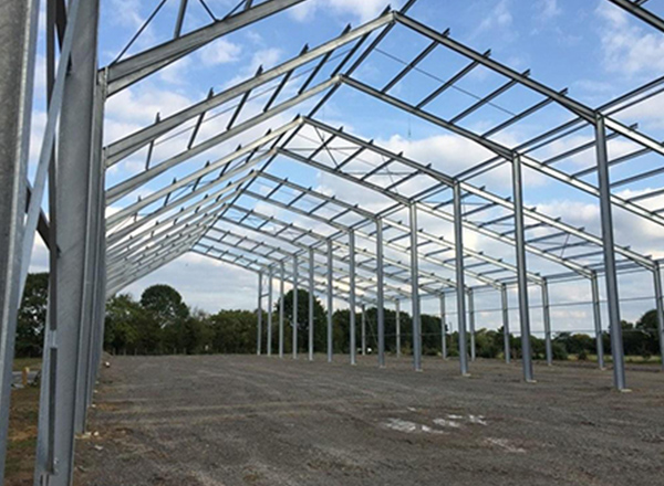
The steel columns can only be installed after the concrete has fully solidified and has strength. After the steel columns are installed, the verticality and elevation of the steel columns need to be adjusted, and then the supports between the steel columns should be installed. Then install steel beams, purlins, purlin supports and other components. It should be noted that all components are connected by high-strength bolts. After the skeleton installation of the warehouse building is completed, the roof and walls can be installed. Finally, the doors and windows are installed, and the warehouse can be put into use.